Category Archives: Project

Super Chook House Mk2 – A most Egg-cellent Construction

TL:DR; A chicken coop was built to replace an existing one. The new one was made from recycled pallets. This had to be done in time for the local Council curbside rubbish collection, which had been booked two months before.

The Build

On 18 November 2024 I was able to complete the construction, less a couple of features, of the Super Chook House Mk 2.

The original Super Chook House had been purchased online sometime in 2018. I don’t recall all the details, but it came flat packed and in all probability been make somewhere oversees. It was made in a light wood, probably western red cedar, and looked like a small cottage including a chimney. It still needed to be painted, which caused a two year delay, given all the other things going on, before it was able to host our first flock. (More details in in the link above.)

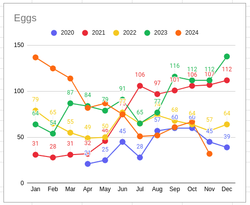
Egg Production – Apr 2020 – Nov 2024

Egg production began in April 2020.

The chickens have been a great edition to the family and have been both a great source of eggs and entertainment. They have somehow managed to avoid “sanctions” as one needs to be ever vigilant, as the little dinosaurs will, without hesitation, exploit any gaps in the fencing to raid unprotected vegetables in the garden. It is a fair trade.

It has been four and a half years, and the painting didn’t really work everywhere. The roof had rotted out on one edge, but it all came to a head when the floor fell out. A new chicken coop was required. The Super Chook House Mk2 project was hatched but was there a alternative, a better option, to the previous version? I don’t know how long it would take to fix, but I don’t think the chickens would be able to cope with another two year delay. I’m sure they would, after all they’re chickens, but it certainly wouldn’t be the best solution, and this was an opportunity to try something different.

There were parts of the original coop that could be reused. The original kit came with an enclosed cage, which was meant to be bolted onto the side. Due to the painting, which was never completed for this part, this feature never got added. Instead, the mesh panels ended up being used for vegetable protection technology, protecting them from the chooks and other raiding avians. I’m looking at you, blackbirds!

Other reusable parts included: the large metal tray in the base of the coop (although this has been found to have rusted through, so an alternative is required); the nesting boxes, with their own tray inserts; the ramps into the coop; and the roosting rails.

The Design

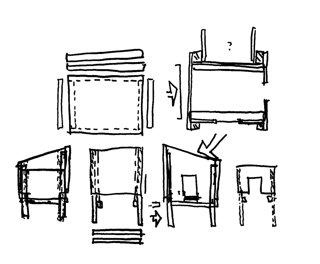
Rough Design

A local council curbside rubbish collection was booked, so the clock was now ticking. Two months to go.

Design work began, on and off, in the evenings in front of the TV (old school).

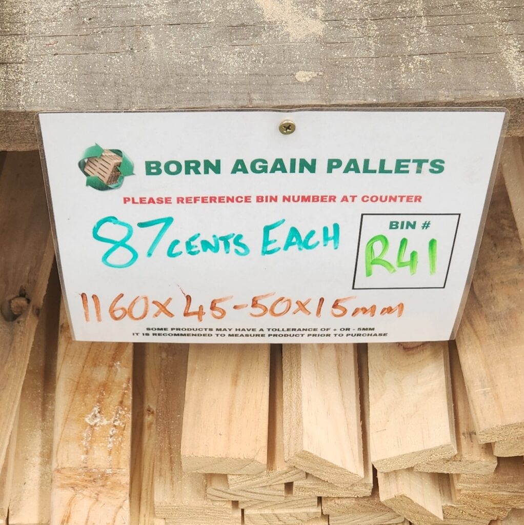
The plan was always to try and make use of recycled wood from Born Again Pallets. This Adelaide business breaks up and sells the materials from wooden pallets (it’s in the name) but I have also seen this material used in other community projects (Video: Microbat Nesting Box Workshop). Bunnings had blog posts of similar chicken coop projects using recycled timber (Chicken Coop, Nesting Boxes). I won’t pretend that I have the skill of these master wood workers, but I have a jigsaw, so how hard can it be? I don’t think I will need the router for this project.

The design went through several iterations. where the plan was to provide a chicken coop similar to what I had (size, features) but made as simply and easy as possible, made out of material which would hopefully last a little bit longer.

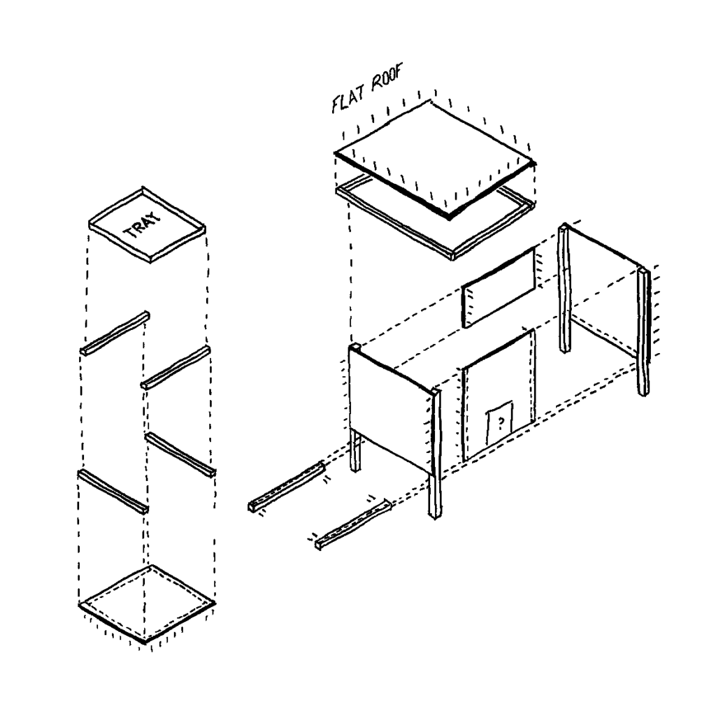
Isometric Construction View

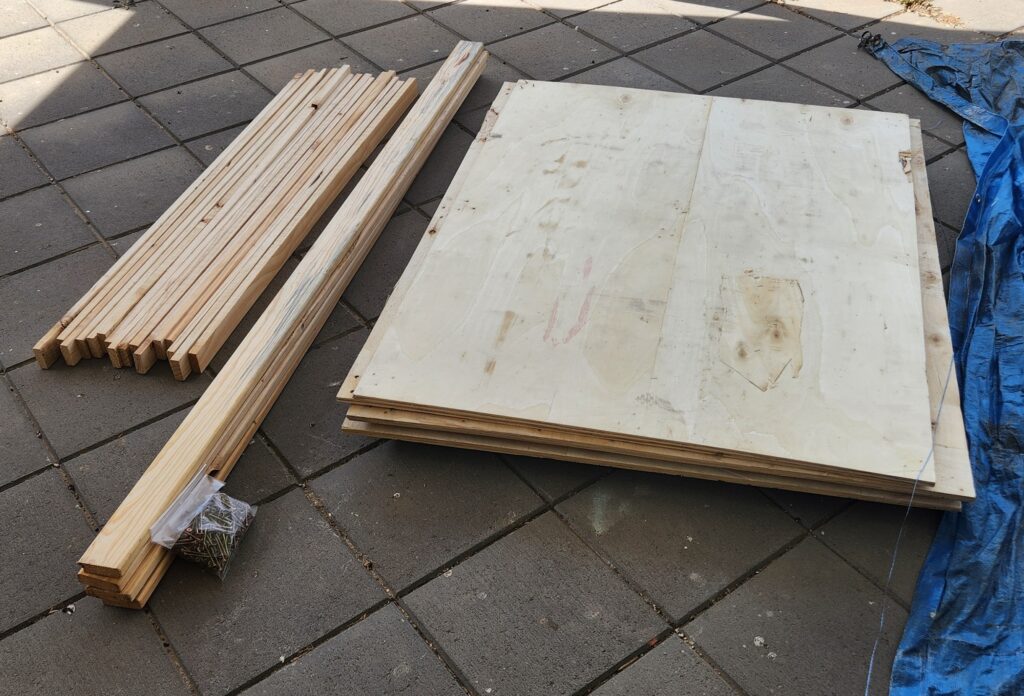
In the end, the plan needed 6 sheets of plywood, for the sides, floor and roof, 4 posts for the legs, and additional batterns for edging the floor tray and the roof. The size was based around the existing metal floor tray, with other measurements taken from the existing coop. Leg height (500mm), Nesting Box height (350mm) and Doors (350x300mm). The height was taken as the maximum size allowed by the plywood sheets, and the roof pitch was chosen to be about 30 degrees.

The calculation of the maximum possible roof angle, given the size of a plywood sheet, was outsourced to the family’s year 11 student, who made use of their trigonometry knowledge to confirm that this was possible.

Part of the larger plan is to also mount a solar panel on the roof to power some sensors etc. so the the coop was to be orientated with the slope of the roof facing north.

Getting the wood

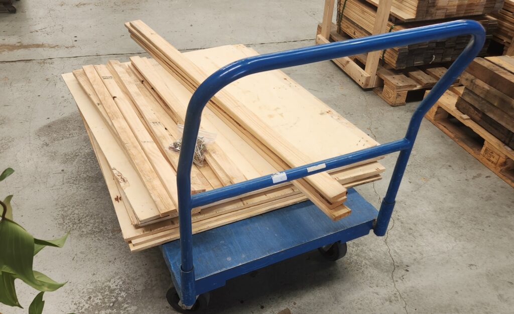
With a design in mind, it was off to Born Again Pallets so see what material they had. Time had also run out. This shopping trip was on a Friday, and the Council rubbish collection was booked for the next Tuesday, so everything was going to be done have to be done in one weekend.

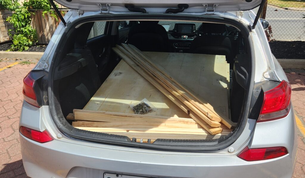
It was a successful trip. Even though some compromises were made, all the required materials were purchased, including a packet of screws.
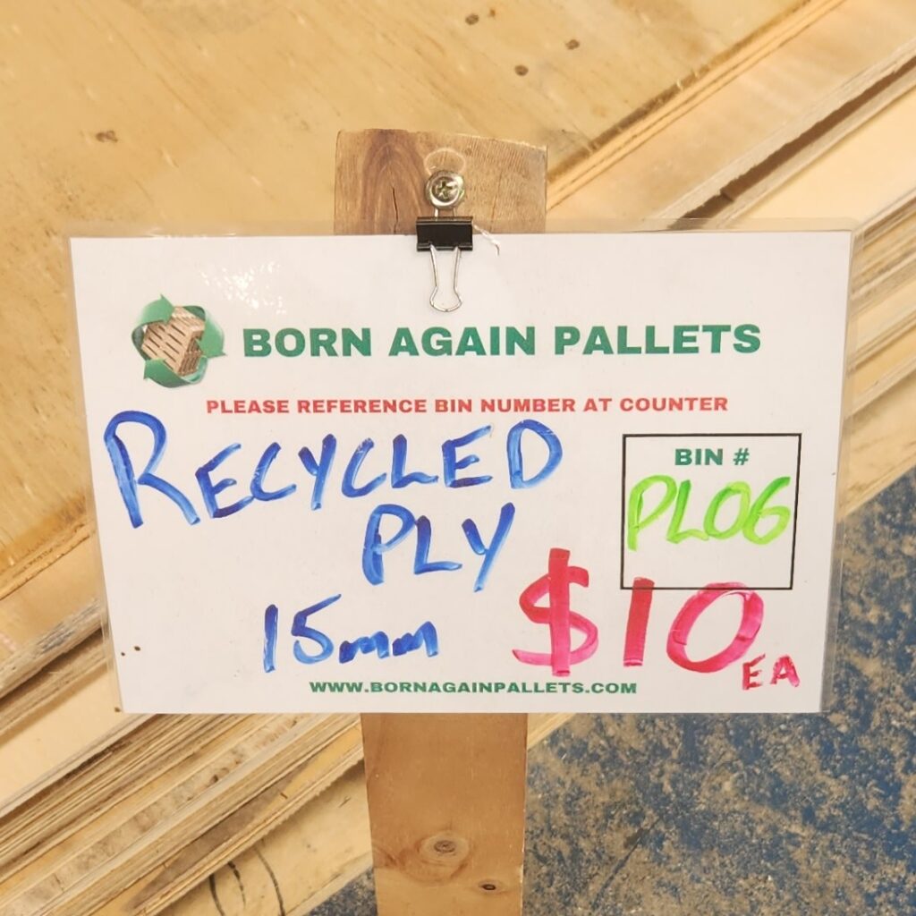
A trip to Bunnings was also made to pickup some timber oil, which was applied to the plywood. It was hoped that this will allow the wood to last a little bit longer and it also included some anti-bacterial properties. We will see how this goes.

Construction
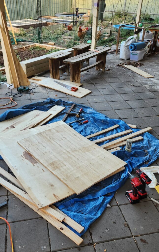
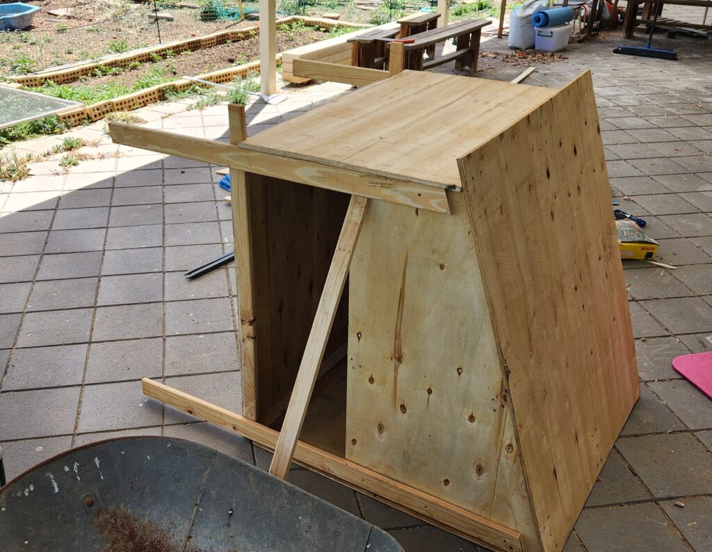
So, over a couple of intense days, and with some help from some interstate visitors (thank you Tim!), the new coop was constructed.

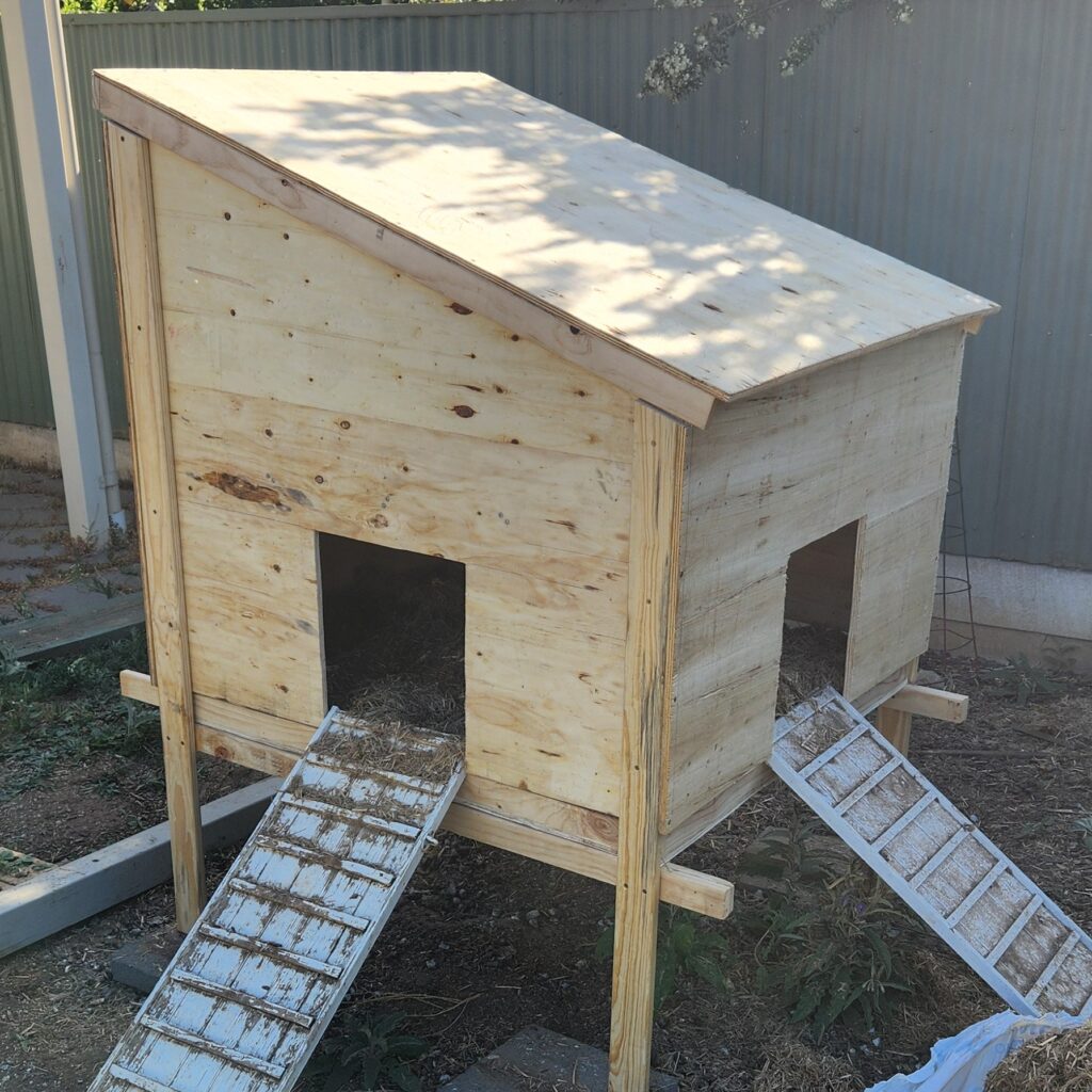
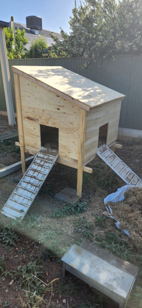
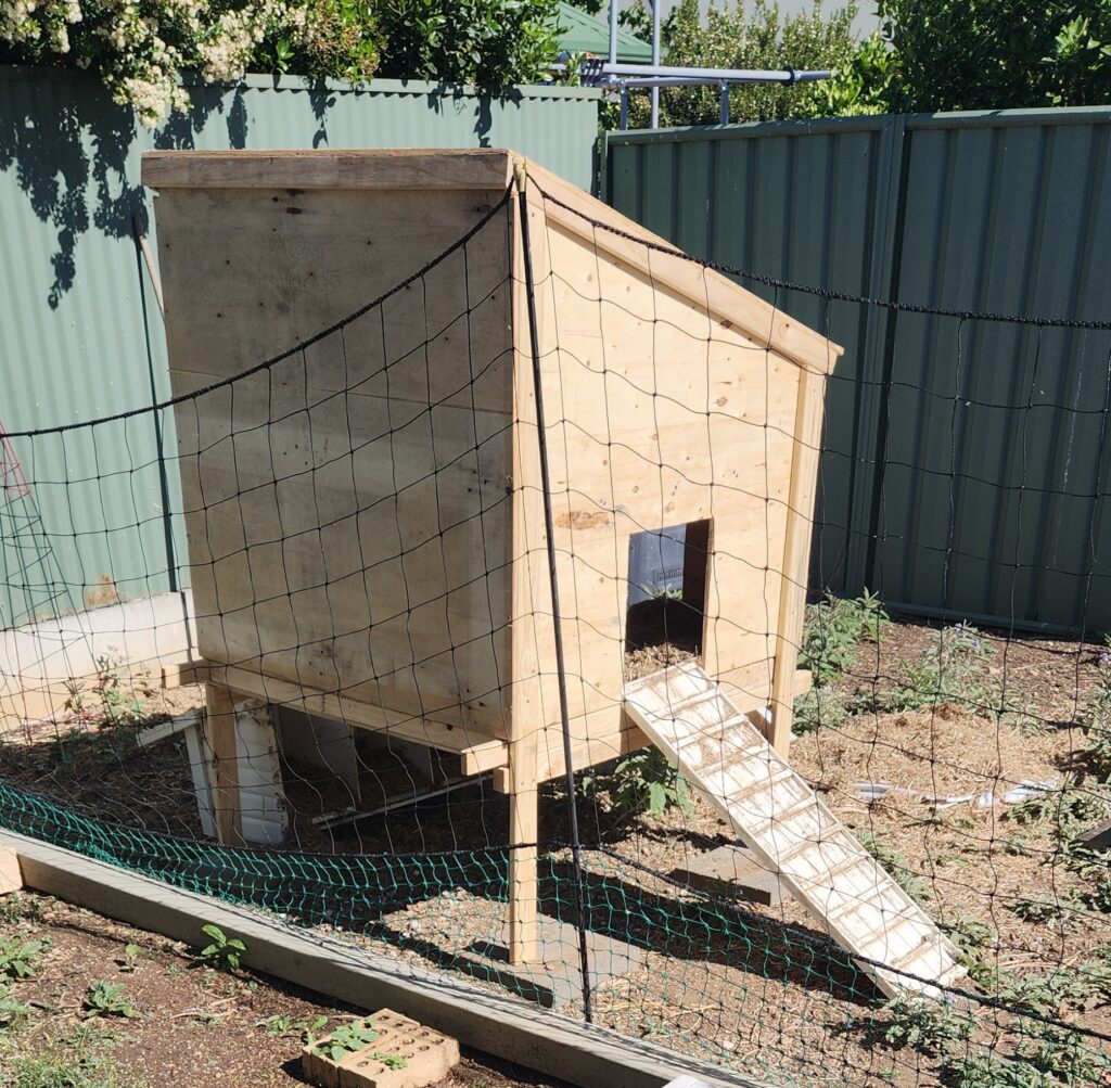
The completed Coop

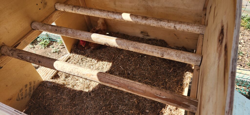
It was very much a fit as you go type of project. As mentioned, the design was based around the size of the metal tray floor of the previous coop. A drawer for this was constructed, and then the walls and roof were then added to fit around this. Pieces were tacked together to confirm the fit, before completely fixing everything in place. The previous roosting rails were also mounted inside.

It has all come together, a lot better than I had hoped.

So, in the evening before the council curbside pickup, the old coop was hauled out to the curb. It was replaced with the new one, reusing the existing ramps, and with some sugercane mulch was all ready for use.

Some Final Comments

The design was found to be fairly robust. The long freehand jigsaw cuts, which didn’t make for the straightest of edges, didn’t compromise the final outcome. The floor slides easily out for cleaning, and the coop is now also accessible from the top as the roof lifts off.

The old nesting boxes still need to be attached to the side (using the original bolts). If more access is required, an access panel could be added to the large wall.

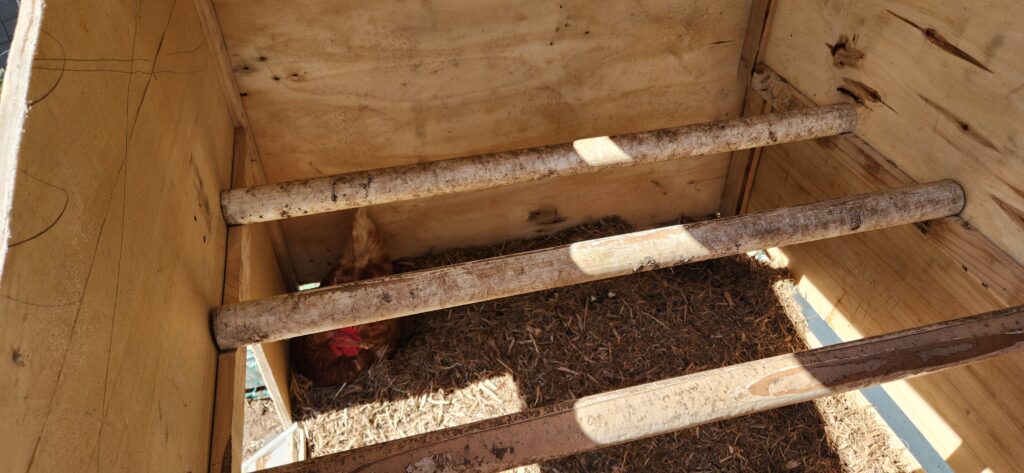
The chickens appeared to have enjoyed their first night in the new digs. I didn’t hear any complaints. See the images below, where ‘Pants’ is making use of the new facilities.
Recording your Energy Meters with Home Assistant

Introduction

This post is about how setup Home Assistent to gain a greater understanding of how you use the energy in your home. These instruction are for if you only have is a regular electricity meter, without having additional power monitoring installed. (Installing additonal power monitoring typically requires the services and costs of an electrician.) It is possible to manually record your daily power usage from your meter and enter it into Home Assistant.

NOTE: It is possible to use just an ‘input_number’ to get the data and display it on the screen in Home Assistant, and display it in graphs etc. Unfortunately, this data is only currently maintained for 10 days and is then dropped. Using a ‘sensor’ template will treat this data like a regular sensor.

Also

  • If automated monitoring is available later then this setup can be used to give you even more insight (with minimal changes);
  • Individual device monitoring can be added though the use of relatively inexpensive ‘Smart Plugs’ which both allow remote switching control of appliances, and individual appliance energy monitoring.

The following instructions assume that you have an operational ‘Home Assistant’ system (it is very easy to obtain, install and configure if you don’t), and are able to make use of the ‘Energy’ dashboard. Some familiarity with Home Assistant is also assumed. (Home Assistant is availble as a downloadeble system image for the RaspberryPi, as well as fully installed system in the Home Assistant Green).

Note: As this meter reading process is a manual version workaround of an eventual automated system, the time of the input of the reading into Home Assistant is taken as the time of the meter value. This needs to be kept in mind, as this timestamp is used to calculate daily usage etc. so it isn’t possible to record a set of readings and then input them at a later date. It is best to enter them into Home Assistant as soon as possible.

Daily Meter Readings

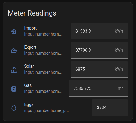
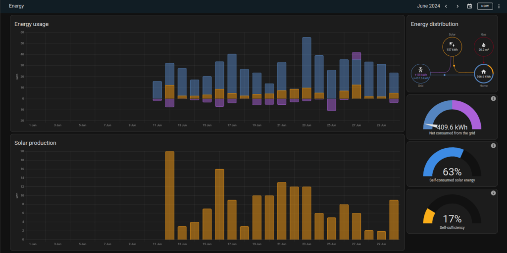
While Home Assistant is designed to be used with an automated meter reading system, it is still possible to get data and make useful observation with daily meter readings. The following describes how to set this up. The final result will be a meter reading dashboard with data entry fields, and a energy dashboard that can display the energy usage of the household over an extended period, say a month or a quarter.

The process is then:

Manual meter reading
--> Data entry into Home Assistant
--> Display household energy usage.

The example installation that this article uses is a household with a bi-directional electricity meter (records and displays power import and export separately), with solar panels and an inverter with an energy production meter.All of these are displayed in kWh.

It is possible to use the same method to add addition meter readings, and the example shows that this has also been done to record the gas meter reading and daily egg production.

Note: Using the ‘total’ meter reading, rather than a ‘daily’ value, ensures that
possible errors caused by the meter reading process are minimised. Any error in
a reading will be ‘fixed’ by a correct subsequent reading.

These instructions are for Home Assistant – 2024.7.1. As Home Assistant is under active development, this may change.

Getting Started

Home Assistant will need several entitles configured for each meter being recorded.

The first meter that we will consider is for electricity from the grid, which we will call “home_electricity_import”. Additional meters to consider will be “home_electricity_export” (excess energy sent back to the grid), “home_electricity_solar” (energy produced by the PV system), “home_gas_import” (gas meter readings) and “home_product_eggs” (how productive have my chickens been) and are added in exactly the same way.

We create an ‘input_number’ entity for recording the meter reading, and then create a ‘sensor’ entiry (via a helper/template) which makes the reading available to the rest of the system as a sensor.

Add a ‘input_number’ entity

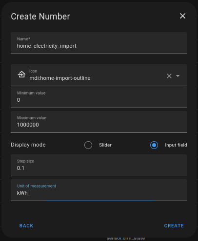
Create an ‘input_number’ entity for entering the meter reading with the following. From:

Settings 
-> Devices and Services
-> Helpers (top menu)
-> CREATE HELPER
-> Number

then press ‘Create’

The entity that is created has the full name of “input_number.home_electricity_import”.

After the entity has been created, the details can be edited by selecting from the entity screen in “Devices and Services” and clicking on the ‘configuration’ (cog) button.

In addition to the above parameters, this screen allows you to allocate the entity to an Area, or allow integration with voice assistants, amongst other things.

The meter reading can updated in Home Assistant by entering the new value in the field displayed when the entity is selected. The time of the input is used as the time of the reading.

(Setting up a dashboard to allow data entry will be described shortly.)

Add a ‘sensor’ entity based on the meter reading

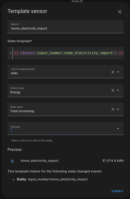
We now need to create an entity with uses the value from the meter reading, and can be used in the Energy dashboard.

Similarly to the last step, we wantot create a ‘templete’ sensor from the helper
menu.

Settings
-> Devices and Services
-> Helpers (top menu)
-> CREATE HELPER
-> Template
-> Template a sensor

then press ‘Submit’

The entity that is create has the full name of “sensor:home_electricity_import” and should have automatically picked up the value of the meter reading.

The icon for the entity is automatically picked up from the ‘device class’ but can be changed in the entities ‘configuration’ screen.

Add entities to a dashboard

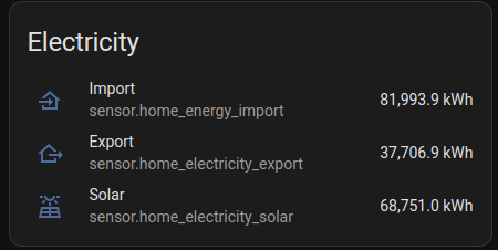
Before we attempt to setup the built-in Energy dashboard, we can check that everything is working as expected by usung two entity cards, one to display the ‘input_number’ and one to display the associated ‘sensor’ entity that we have just created.

  • input_number.home_electricity_import
  • sensor.home_electricity_import

Note: The card for the ‘input_number’ should display a data entry field, where
you can enter the current meter reading. When you do this, the ‘sensor’ card
should automatically change to reflect the new value entered.

Repeat for more meter readings

In the previous setup, whereever ‘home_electricity_import’ is used, replace this
with the name of new meter to be configured, and repeat the steps.

Energy Dashboard

With the meter readings now being recorded, it is possible to import the data into the Energy Dashboard.

To configure

Menu: Energy 
-> … (top right menu)
-> Energy Configuration

Then

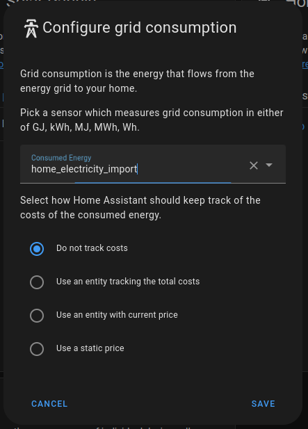
Electricity grid -> ADD CONSUMPTION

then press ‘Save’

Note: It is possible to create entities to track the existing energy price
“home_energy_import_price” in AUD/kWh. This is left as an exercise for the
reader.

If the other meter reading entities have been created, then they can also be
added in a similar way,

Electricity grid -> ADD RETURN
Solar panels -> ADD SOLAR PRODUCTION
Gas consumption -> ADD GAS SOURCE

Note: The gas meter reading for my meter measures the gas in m^3. The bill is
charged by kJ. Your gas bill should show the factor that is used by the gas
company to make the conversion from volume (m^3) to energy (kJ).

The energy dashboard should now start recording your energy usage. It will take
a while (possibly up to an hour) to register a new meter reading each day, but after a while you will now be able to see you energy usage and generation broken down by day, month etc.

Note: There is nothing stopping you recording meter reading more often than
daily. It may be interesting and worthwhile doing a day of hourly readings to
determine where the daily peak periods are.

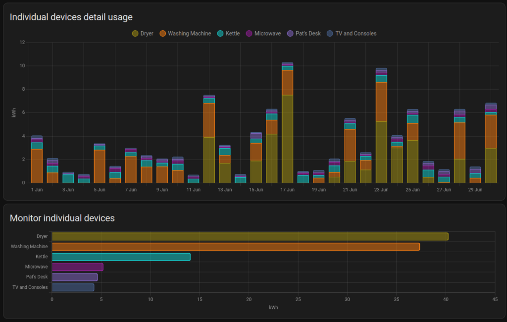
Energy use of individual appliances

The energy dashboard also allows monitoring data for individual devices to be
added to the display. I use the Athom Smart Switch v2 ESPHome (there is also a new version based on the ESP32-C3). These Smart Plugs, once connected to your Wifi network, are automatically detected by Home Assistant what can then monitor and control these devices.

Automating the Manual Meter Reading

It the reading of the meter can be automated and fed into Home Assistant then
manual meter reading will no longer be required, and the reading can also be done much more often.

Once the data is being read into Home Assistant, via a meter reading
sensor entity, the template sensor we created can be modified to use this new sensor instead of the ‘input_number’ entity.

Note: Some finessing may be required to match the new meter reading with the old
ones eg. by adding or subtracting a fixed ‘offset’ amount.

Digression (and Rant) about Automated Meter Reading in Australia

<rant>

For many of the electricity smart meters around the world, there are Home
Assistant integrations which allow their data to be read automatically, possibly
as often as every 10 seconds. These were originally designed for in-home energy displays, and some countries even mandated a standard for this (eg. the P1 port on the Netherlands)

In Australia, unfortunately, the smart meters that are being installed in the
National Electricity Market(NEM) do not come with this feature. For electricity
customers, AEMO (the market operator) is relying on the Energy Retails to supply
this information to their customers, but this customer data is typically only
made available the next day after the ‘market settles’ (typically 24 hours
later).

One solution is for individuals to install their own energy monitoring meter,
inline and behind their electricity providers meter. This allows a home owner to
capture the data that they need, but comes with its own issues.

  • the installation requires an electrician;
  • the meter readings may not agree with the existing meter, and would not be
    accepted by the energy supplier in a dispute;
  • it isn’t (easily) possible this way to take the monitoing wigh tyou if you move house;
  • it would a difficult option for a rental tenant;
  • it adds another point of failure into the home network

In Australia there is also a commercial market with product lines dedicated to providing this missing functionality. A lot of these products also put your data into the cloud, which can then be used by the collecing service to sell to other businesses.

Your power usage should be made available to you as you use it, and not 24 hours after the event, and this should be available to all consumers by default.

All electricity customers are currently paying for smart meters in their electricity bills as there is a smart meter allowance included in the “default market offer” (DMO) which is used by the energy retailers for creating that energy plans on th eNEM.

Changing this for consumers does not appear to be a priority for anyone involved
in the industry.

</rant>

Update: It appears as though there are particular models of Smart Meter being used in Victoria that has a Zigbee based “In Home Display” that can provide this functionality.

Building a cheap-n-cheerful Quirkey one-handed keyboard

The Setup

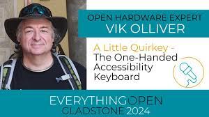
At the recent Everything Open Conference, I attended a taik by Vic OIiver on the one handed keyboard called the Quirkey.

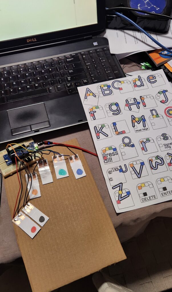
I am attempting to write this blog post using a version of this keyboard I have made out of cardboard, a Arduino MKR 1310 board and some other bits and pieces of stuff that I found lying around the house. (I am going to have to stop here and go back to my regular QWERTY keyboard. I will have another practice later, but at the moment I am finding that I am using the ‘backspace’ more than I would like to.)

The details of Vik’s presentation are here, the code (https://github.com/VikOlliver/Microwriter) and documentation (https://github.com/VikOlliver/Quirkey) are available in Github.

While looking into the Arduino code, it occured to me that I had a dev board that would actually work with this code (the Arduino MKR 1310 which had been used in a previous project). In particular, this board supported the HID, and Keyboard and Mouse libraries, which is what allowed this board to appear as (surprise, surprise) a keyboard and mouse device when plugged into a USB port. There ae many naferious project ideas for this sort of technology, but I don’t think that the usefulness has been explored enough.

The Design

This project code takes the corded (multiple symaltanious keypress) inputs, of six buttons, and converts it into regular keyboard input. Vik’s presentation gives more of the backgound, and reasons why knowing how to use one handed keyboard is a good skill to have. In addition, the documentation includes helpful tools to assist in learning this skill, as will as a typing tutor.

So… I have an Arduno board that will do the job (there is a good list of supported boards on the HID Library page), I just need to get some switches.

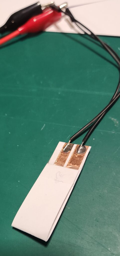
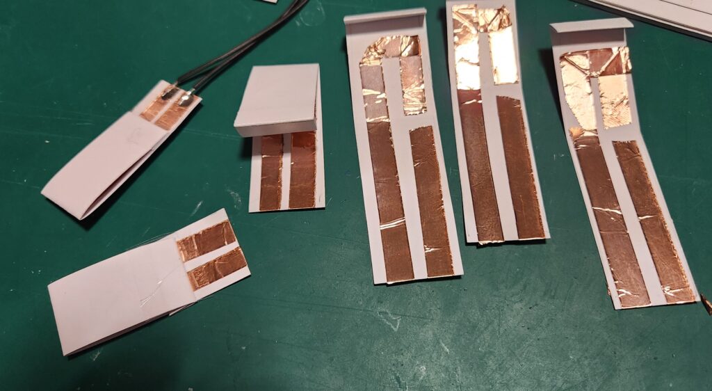
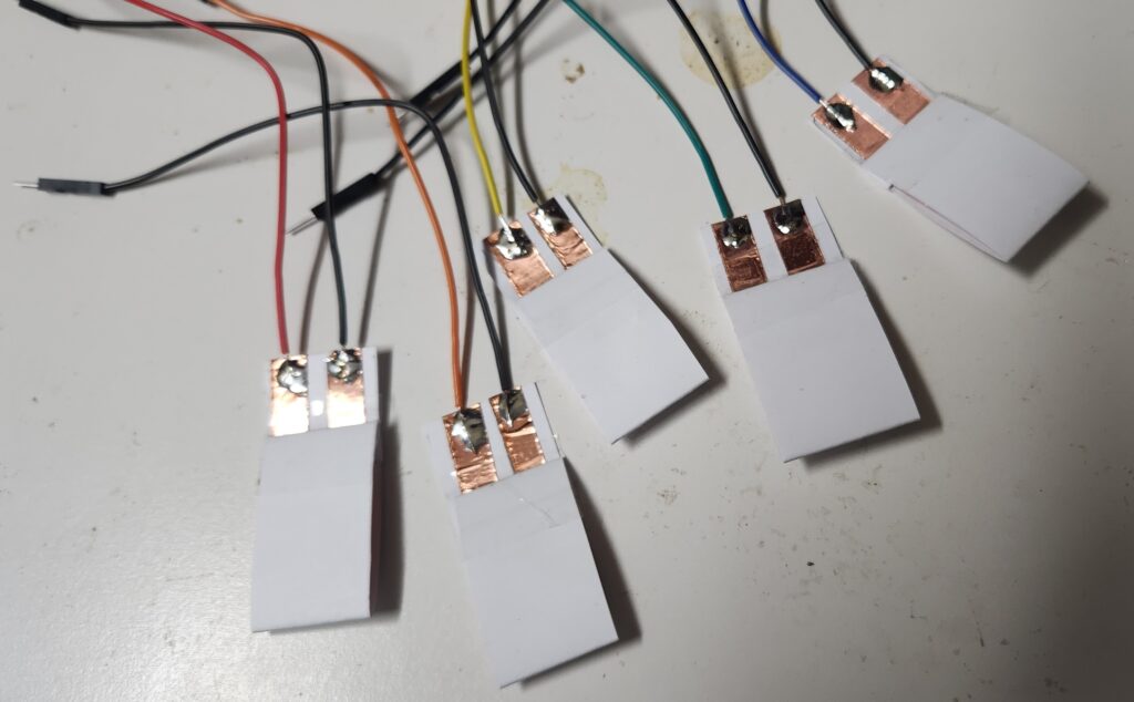
The latest version of the Quirkey keyboards were the result of lots of trial and erro experimentation, and consited of a 3D printed shell with six mechancal switches. My Prusa printer is currently broken and I didn’t have any unused mechanical switches within reach, but I did have some cardboard, copper tape and my trusty soldering iron. So, after some of my own experimentation, we get the following design…

The cardboard switches are stuck down onto a piece of cardboard, wired up to the Arduino MKR 1310 board (any MKR 1000 series boar will work), and programmed with the MicroWriter Ardunio sketch. (Comments in the sketch indicate which pins connect to which switch.)

There is a 5 second delay on startup, but the board is now detected as an “Arduino LLC Arduino MKR WAN 1310 Keyboard” and “Arduino LLC Arduino MKR WAN 1310 Mouse”, and works as advertsed.

Conclusion

This is a great cheap-n-cheerful project incorporating a bunch of useful ‘maker’ techniques (soldering, wiring and Ardunio programming) which can be completed resonably quckly.. and at the end you get something useful to play with.

The switches aren’t perfect, but it’s great to have something to use to learn the one handed keyboard technique.

After practicing for a while, for not much more, the paper and copper switches and cardboard can be replaced with something a little more permanent. (A project for the future.)

Getting the Heltec Wireless Lite V3 with SX1262 LoRa Radio Chip to work with LoRaWAN

This article is part 1.5 of the series – Developing a component for ESPHome, for the SX1262 LoRa Radio Chip. The process getting the LoRaWAN functionality of this development board to work with The Things Network proved to be an excercise infrustration management, so the following is a write up of what was required to get it to work. The following is my account of setting up the Heltec Wireless Lite V3 for
connecting to the LoRaWAN network. There were several false starts, but in
the end it was possible to send data and decode it correctly.

Development Environment

ArduinoIDE and the Heltec Board Manager extention

The Heltec boards are defined by the following file (link) which is added through the menu in Preferences…->Additional boards manager URLs

https://github.com/Heltec-Aaron-Lee/WiFi_Kit_series/releases/download/0.0.7/package_heltec_esp32_index.json

This file specifies that esptool 3.3.0 is used for writing the firmware to the Heltec board. There is as issue with usung this version for the Heltec V3 boards, in that the firmware compiles and installs, but puts the ESP32-S3 processor into a boot loop.

The details of this issue is here: https://github.com/Heltec-Aaron-Lee/WiFi_Kit_series/issues/159#issuecomment-1842269504

The fix is to upgrade esptool 4.6.1. The following fix works on Ubuntu, but
it’s a hack. The correct fix would be to change the JSON definition file.

cd ~/.arduino15/packages/Heltec-esp32/tools/esptool_py
mv 3.3.0 3.3.0-bak
wget https://github.com/espressif/esptool/archive/refs/tags/v4.6.1.zip
unzip v4.6.1.zip
rm v4.6.1.zip
mv esptool-4.6.1 3.3.0

LoRaWAN Library

Install the ‘SX126X-Arduino’ library with the library manager (currently version
2.4.0).

A small fix is required. Edit the ‘src/mac/Commissioning.h’ file and comment out the check for whether the LoRaWAN Region has already being set (Line 40).

Example Code – LoRaWAN.ino

From the LoRaWAN library, the LoRaWAN example was copied and modified to get the
system to work.

Modifications:

  • Copy the LoRaWAN.ino file, and remove other unnecessary files. Fix the source to remove the dependancies.
  • Simplify the code. eg. Remove the code sections used for other processors.
  • Set the authentication mode to OTAA, the device type and the Frequency bandplan region to AU915 by adding the optional parameters to ‘lmh_init() – true, CLASS_A and LORAMAC_REGION_AU915.
  • Ensure that the correct LoRaWAN sub-band is being used for AU915 by calling ‘lmh_setSubBandChannels(2)’.
  • Additional Serial.println() output added to trace the execution of the firmware, including the output of the LoRaWAN parameters.

The LoRaWAN parameters (AppEUI, DevEUI and AppKey) are set in the following section.

The Things Network

The Heltec V3 Devices have not been configured as known devices in The Things
Network
, and need to be specifically setup.

Select “Enter end device specifics manually”.

Add a new device and set the following Device Parameters

  • Frequency Plan: Australia 915-928 MHz, FSB 2 (used by TTN)
  • LoRaWAN Version: LoRaWAN Specification 1.0.2
  • Regional Parameters version: RP001 Regional Parameters 1.0.2 revision B

Create a JoinEUI (previously known as the AppEUI). This can be freely set any 8-byte value, but cannot be changed once set.

The other parameters that need to be set are:

  • DevEUI
  • AppKey

The easiest way to to get these values is to allow them to be automatically generated by The Things Network interface. They can be specifically set if the manufacturer of a device has preprogrammed a device with a LoRaWAN configuration.

Build and Install Firmware on Device

Update the definitions of the LoRaWAN parameters in the code to reflect the values just generated. It is possible to directly produce the desired strings (in ‘msb’ format) from The Things Network device interface.

Paste these into the code

uint8_t nodeDeviceEUI[8] = {…};
uint8_t nodeAppEUI[8] = {…};
uint8_t nodeAppKey[16] = {…};

Ensure that these parameters are being set in the ‘setup()’ function with the following:

lmh_setDevEui(nodeDeviceEUI);
lmh_setAppEui(nodeAppEUI);
lmh_setAppKey(nodeAppKey);

It is also helpful to also have these values displayed when the board os booted.

The firmware compiles and can be installed onto the Heltec board. On boot, it should
connect to the LoRaWAN network and start transmitting packets of data.

On The Things Network, to check that the uploaded data is correct, the following JavaScript payload filter can be installed for the device, which will decode the data and
(hopefully) display the correct string.

function decodeUplink(input) {
var result;
result = String.fromCharCode.apply(null, input.bytes);
return {
  data: {
    bytes: input.bytes,
    result: result
  },
  warnings: [],
  errors: []
};
}

Notes, Issues and Errors

  • When selecting and playing around with different LoRaWAN Versions and Regonal Parameters, it appears as though The Things Network does not reset LoRaWAN values properly. Changing the LoRaWAN version to 1.1.0 required the additional parameter ‘NwsKey’. If the LoRaWAN version is then set back to 1.0.2, this value becomes the one that is used for the AppKey. There is a note about this in The Things Network interface, but it is not obvious what is required.
  • Care needs to be taken when setting the nodeDevEUI and nodeAppEUI not to set them the wrong way around. If connection packets are being received from the device, but it isn’t able to authenticate, then the nodeDevEUI will be correct, but the other parameters (including LoRaWAN Version) may be wrong.
  • If only intermittent transmitted packets are seen in The Things Network, and the device is not able to authenticate, check that the firmware has selected and is using the correct LoRaWAN sub-band.
  • Selecting other LoRaWAN versions eg. 1.1.0 will require additional parameters to be set., namely NwsKey. This setting is not removed if the LoRaWAN version is set back to 1.0.2, and this value is then used instead of the nodeAppKey. This is a trap. The only way to fix this is to delete the device definition in The Things Network and start over.

Next Steps

  • Convert the Arduino LoRaWAN firmware to ESPHome. This will allow LoRaWAN to be able to be used with the other ESPHome functions, including support for all of the existing supported sensors and outputs, and also operate with Home Assistant. (This will be Part 2 of the “Developing a component for ESPHome, for the SX1262 LoRa Radio Chip” series.)
  • Test with the Helium network. Register the device on the Helium network and check that data is routed correctly.
  • Implement as Class B and Class C LoRaWAN device. The example code currently only
    uploads data. Class B and Class C deviced allow data to be downloaded as well, for device control.

Installing ESPHome – A Quick Start Guide

These instructions are summarised from the online instructions. See: https://esphome.io/guides/installing_esphome.html

Quickstart

Installation

The following installs ESPhome on a Windows computer so that it can be run from the ‘cmd’ window (text input).

Install Python (and Pip)
See instructions here: https://www.python.org/downloads/

Ensure that option “Add Python to PATH” is selected before installing the package.

Check that Python is installed

In a Windows ‘cmd’ window (command prompt).

python --version
=> Should return something like: Python 3.10.1

Install dependencies

pip3 install wheel

Install ESPHome

pip install esphome

Check installation

esphome version
=> Should return something like: Version: 2023.12.0

ESPHome is now installed, and can be run from the Windows CMD

Using ESPHome

Create/Edit YAML files

ESPHome is driven via YAML configuration files in the working directory. YAML (Yet Another Markup Language) files are text files which are formatted in a specific way. They can be edited with any tool which can edit text files. (MS Notepad is good, MS Word may cause problems. MS Visual Studio (Code) is a good place to start.)

Once installed, view available ESPhome options

esphome -h

A simple YAML file that works with the Heltec Wifi LoRa 32 V3, which can be extended, looks like the following. (Copy and save this file as ‘esphome-device.yaml’) To understand the parts of this fle and the YAML configuration options, see: https://esphome.io/

esphome:
  name: "lora-sx126x"

esp32:
  board: esp32-s3-devkitc-1
  framework:
    type: arduino

logger:

wifi:
  networks:
  - ssid: WIFI_SSID_GOES_HERE
    password: WIFI_PASSWORD_GOES_HERE
 
ota:
  password: OTA_PASSWORD_GOES_HERE

# Enable Home Assistant API
api:
  encryption:
    key: API_KEY_GOES_HERE

web_server:
  port: 80

With an ESP32 board, new firmware can be built and installed using a YAML configuration file with:

esphome run esphome-device.yaml

These commands can be run individually as the following.

esphome compile configuration-file.yaml
esphome upload configuration-file.yaml
esphome logs configuration-file.yaml

When the program is running, it can be interupted by pressing the key combination: Ctrl-C

Over the Air (OTA) Updates

If enabled in the YAML file, ESPHome also supports “Over the Air” updates. This means that if the ESP board is currently connected to a Wifi network then using this connection, it can be directly upgraded with new firmware.

This option can be selected during the ‘upload’ step. If the board is not connected with USB and only connected to Wifi, this will happen automatically.

Additional notes – For Linux Users

Using a Virtual Environment – venv

The above process is very similar when installing on Linux or MacOS. On Linux, it is possible to setup a ‘virtual environment’ (venv) for development by installing and using the ‘venv’ command. This will allow the local Python libraries to be installed and run separately to the system libraries. This is useful to allow the development environment to use more recent library versions and/or allow the development environment to use more stable version. This helps when debugging and tracking down issues that may be caused by libraries.

Ensire that you are working in the required local project directory (eg. with the ‘cd’ command)

With Python and Pip installed as installed, create the venv development environment in the current working directory.

pip3 install venv
python -m venv venv
. venv/bin/activate

Install and run ESPHome as before.

To restart editing session in an existing venv enabled directory

Setup the venv environment again by using:

. venv/bin/activate

At this stage, it is also possible to install ESPHome directly from the GitHub
development repository. This is useful for debugging, bug fixing and testing.

Install development version from the Github ESPHome repository

This requires that the ‘git’ lool has been installed. (Use ‘apt git install’ on Ubuntu.)

git clone https://github.com/esphome/esphome.git
cd esphome
python -m venv venv
. venv/bin/activate
./scripts/setup

As required, update the local copy of the code with the following.

git pull
./scripts/setup

Developing a component for ESPHome, for the SX1262 LoRa Radio Chip – Part 1

Introduction

This post describes “Work in Progress”. I have deliberately decided to put these details together now as it has been possible to build something that ‘sort of’ works, in that all the pieces are there, ot nearly there. The end is in sight, albeit a reasonably long way away in time and effort.

The original aim was to make the SX1282 LoRa radio chip available, for both LoRa and LoRaWAN modes, directly in ESPHome. It is hoped that the use of the SX126X series of radio chips can be as easy as possible to use and in most cases wholly driven from the ESPHome YAML files. When creating an IoT device with a new dev board, this has been one of the frustrating pieces of the excercise, particularly when using the Arduino IDE and programmer.

The Github repository of the component is here: https://github.com/PaulSchulz/esphome-lora-sx126x

These notes assume that you have ESPHome installed (

To include this external component in your own ESPHome yaml file, see below, or read the repository’s documentation (which will be newer than this).

Hardware

This ESPHome component is being developed on the Heltec V3 Development Boards which use the LoRa SX1262 chip. These dev boards are:

At the present time, these boards are not available for selecting directly in the
ESPHome YAML file (when using the Arduino framework). In order to make these
boards work with the available version of ESPHome, the following YAML is required:

esp32:
  board: esp32-s3-devkitc-1
  framework:
    type: arduino

These board definitions are imported from the platform-espessif32 project here.

The LoRa Arduino Library

The Arduino library being used is beegee-tokyo/SX126X-Arduino, which itself is based on several other libraries. It appear to currently be the best and most maintained LoRa library available for these radio chips.

The following header file contains the descriptions of the functions and fields used by the library: https://github.com/beegee-tokyo/SX126x-Arduino/blob/master/src/radio/radio.h

Testing and Usage

The files lora-sx126x.yaml and secret.yaml provide an example of how to use the
component. To use with a working version of ESPHome, edit secret.yaml to add
your local Wifi details, then run:

esphome run lora-sx126x.yaml

Development Comments

To get the component into a working state, this ESPHome component currently does some things which are not encouraged by the ESPHome Core and Component developers (see below).

It is always hoped that this component will become compliant enough to be
included in ESPHome, but in the meantime, it can be included in your ESPHome
build by either cloning this repository locally and adding an external_component
with a local source; or by including the github repository directly as an
external_component. See the External Components documentation for more details

If downloading and using as a local source for external component:

external_components:
- source:
    type: local
    path: esphome/components
  components: ["lora_sx126x"]

and, using directly from the Github source for an external component

external_components:
- source:
    type: git
    url: https://github.com/PaulSchulz/esphome-lora-sc126x
    ref: main
  components: ["lora_sx126x"]

Considerations / Things to fix

Direct use of SPI and SX126x-Arduino libraries

If possible, the SX126x-Arduino library needs to be implemented natively in
ESPHome, to make use of the native ESPHome SPI code.

By using the Library directly, it is uncertain at the moment whether this component can be used generally with other devices that use the same SPI interface.

Example YAML

The following is the proposed example YAML configuration, for a ESPHome image that will enable the SX126X radio.

esphome:
  name: "lora-sx126x"
  libraries:
    - "SPI"
    - "Ticker"
    - "SX126x-Arduino"

...

external_components:
  - source:
      type: local
      path: esphome/components

...

lora_sx126x:
  # The frequency to use needs to be specified as will depend on the
  # hardware and the region in which the it is being used.
  frequency: 915000000

Development

Proposed YAML Options

The following is an example of the proposed full option list, for using the LoRa radio chip.

lora_sx126x:
  # optional, with sensile defaults, if possible from board id.
  pin_lora_reset: 12
  pin_lora_dio_1: 14
  pin_lora_busy: 13
  pin_lora_nss: 8
  pin_lora_sclk: 9
  pin_lora_miso: 11
  pin_lora_mosi: 10
  radio_txen: -1
  radio_rxen: -1
  use_dio2_ant_switch: true
  use_dio3_tcx0: true
  use_dxo3_ant_switch: false

  # required - depends on region and frequency band being used
  rf_frequency:           915000000
  # optional (sensible defaults)
  tx_output_power:               22
  lora_bandwidth:                 0
  lora_spreading_factor:          7
  lora_codingrate:                1
  lora_preamble_length:           8
  lora_symbol_timeout:            0
  lora_fix_length_layload_on: false
  lora_iq_inversion_on:       false
  rx_timeout_value:            3000
  tx_timeout_value:            3000

It should then be possible to use the radio with the various builtin types. This has yet to be implemented.

text_sensor:
  - platform: lora_sx126x
    id: lora_message
    name: LoRa Message

# Is there a component for this in ESPHome?
# Sending a string to a component?
text_message:
  - platform: lora_sx126x
    id: send_message
    name: "Send LoRa Message"

binary_sensor:
  - platform: lora_sx126x
    id: lora_sensor
    name: LoRa Sensor
    on_string: "@+++"
    off_string: "@---"

switch:
  - platform: lora_sx126x
    id: lora_switch
    name: LoRa Switch
    on_string: "@^^^"
    off_string: "@vvv"

binary_input:
 - platform: lora_sx126x
   id: lora_input
   name: LoRa Binary Input
   on_string: "@***"
   off_string: "@..."
  
binary_output:
 - platform: lora_sx126x
   id: lora_output
   name: LoRa Binary Ouput
   on_string: "@>>>"
   off_string: "@<<<"

Installing and Running Overleaf (for creating LaTeX Documents)

TL;DR

Instructions on how to install a full LaTeX installation in Overleaf, so that all of the available LaTeX packages can be used.

Introduction

I am using Overleaf to creare LaTex Documents. It is a web based interface which has a text editior and document preview window. It also allows multiple users to colabourate on the same document.

This is my attempt at documentaing my steps in getting Overleaf Community Edition installed on my local laptop so that I can create LaTeX documents. I have used Gummi in the past for writing LaTeX which I liked, but a lot of the LaTeX documentation that a Google search returns is for Overleaf, specifically the Overleaf Pro and Internet based version.

Background

While Internet hosted software applications can be good, they rely on having an internet connection, and that I am happy to share what I am doing with another, very unknown and anonymous system.

On a related note, some of this document has been written by ChatGPT. The irony of this is not lost on me.

This installation uses the most recently available version of the Overleaf Toolkit to install the current version of overleaf available in a docker image (sharelatex/sharelatex, version 4.0.1).

The previous installation processes used ‘docker-compose’ directly, and instructions here reflect that. They were useful in that they included details on how to add additional LaTeX packages. The current installation instructions (Quick Start Guide) are good, but they don’t incluse these details which are also need to subtly different.

As far as I can see, there is no Discord, Slack or even IRC channels for users of the Overleaf Community Edition, which made trying to get some help with figuring some of this stuff out. I was able to get some answers to my questions by searching Github issues, namely overleaf/toolkit/issues/85.

Prerequisites

This installation was done on a Ubuntu 23.04 laptop, which has docker-ce and docker-compose installed and configured so that the user is in the docker group and can run docker commands directly.

Note: It is also assumed that the user has suffient disk space to install and run the software. I start and checkout my git repositories into ~/Documents/git but you may be using another location.

Installation

The initial installation of Overleaf via the Overleaf Toolkit can be done via the folllowing commands (taken from the Quick Start document):

git clone https://github.com/overleaf/toolkit.git overleaf-toolkit
cd overleaf-toolkit
bin/init
bin/up

This last step will take some time to complete as it will download the Docker images and start up the Docker containers. After some time, it is possible to connect to Overleaf and set up the administrator account at http://localhost/launchpad. Setup an account (email address and password), and then login at http://localhost

It is now possible to create LaTeX documents, with the minimal number of available packages.

Adding additional LaTeX packages

With Overleaf running, it is possible to install additonal packages in the container by using the ‘tlmgr‘ command inside the container. For example, to install the gensymb package (so that the \ohm sysbol can be used), use:

docker exec sharelatex tlmgr install gensymb
docker exec sharelatex tlmgr path add

Alternatively, to install all of the available TeX Live packages, use the following. This will take a little bit of time and currently installs 4417 additional packages, providing that there is enough disk space. (With an original image size for sharelatex/sharelatex of 2.72GB, the new image ends up with a final size of 6.38GB.)

docker exec sharelatex tlmgr install scheme-full
docker exec sharelatex tlmgr path add

Once installed, these packages become avalable immediately for use in Overleaf. These installed packages will be ‘lost’ when the Docker container is restarted so the next step is to make these changes permanent.

Commit changes to ShareLaTeX container

To take a snapshot of the installed software, use:

docker commit sharelatex local/sharelatex-with-texlive-full:4.0.1

Instead of local/sharelatex-with-texlive-full, you can chose another image name. Due to the way Overleaf Toolbox works, the version (4.0.1) needs to match the config/version and needs to be in the form X.Y.Z-RC, where the ‘-RC’ is optional.

This command may take a while to run, but once complete, stop Overleaf (Ctl-C in the original window), and change the configuration to use the new image. Edit config/overleaf.rc and change SHARELATEX_IMAGE_NAME to the new image name.

SHARELATEX_IMAGE_NAME=local/sharelatex-with-texlive-full

Restart Overleaf in the background (daemon mode) with the following. This may take a little bit of time to start properly. (I was getting an Nginx Gateway error for a couple of minutes.)

bin/up -d

Conclusion

This documentation very briefly describes the steps required to install Overleaf Community Edition as a self hosted application with additional packages.

Any documents that are created are also stored persistantly on the local filesystem, under the overleaf-toolbox directlry. It is worth periodically downloading documents (as tar backup file) should the entire system need to be reinstalled from scratch.

Also, by default the installation uses port 80 for the web interface, and also supports an SSL configuration. It would be nice to be able to change this so that it won’t interfear with other installed web applications.

Setup and Configuration of a Commercial LoRaWAN Temperature Sensor

Introducton

This document is part of the PAE-IoT Parks and Gardens Project.

The aim of this post is to document the configuration details needed to setup a new temperature sensor which was deployed as part of the Port Adelaide-Enfield Library/Parks and Gardens collaboration, for monitoring the environment around a newly built sports ground and playing surface.

It is a fairly long document and aims to explicitly describe the code that is needed to set up the new data path. It is built on top of the existing data handling system (The Things Network, NodeRED, InfluxDB and Grafana) which has been described in previous posts, so it isn’t a complete explaination of this system.

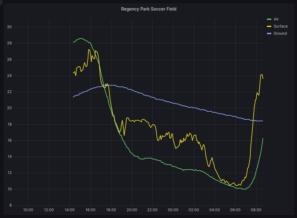
Grafana graph from installed temperature sensors

More details about the project, including the live sensor data, can be found on the project pages:

The Hardware – Temperature Sensor

General information (from The Things Network)

Device Id:       eui-a840416eb183975f
Description:     LSN50V2-D23 LORAWAN WATERPROOF TEMPERATURE SENSOR (3 PROBES)
Frequency plan:  Australia 915-928 MHz, FSB 2 (used by TTN)
LoRaWAN version: LoRaWAN Specification 1.0.3
Regional Parameters version: RP001 Regional Parameters 1.0.3 revision A

Hardware

Brand:            dragino
Model:            lsn50v2-d20-d22-d23
Hardware version: unknown_hw_version
Firmware version: lsn50v2-d20-d22-d23 1.7.5

Note: The LoRaWAN Regional Parameters is set to “Version 1.0.3 Revision A”. This is different to what was found to work with custom developed sensors. It is unclear at this stage what the actual difference is.

The Things Network (TTN) Configuraton

The sensor was easily registered with The Things Network, as the hardware has been pre-configured with a hardware profile from The Things Network Device Repository. This configures the network parameters (as described in the previous section) as well as data formatting functions.

The current Formatter Code returns four data points (Temp_Black, Temp_Red, Temp White, and BatV) and two status values (Work_Mode and ALARM_status).

The code for this uplink data formatting function is as follows:

function decodeUplink(input) {
	var port = input.fPort;
	var bytes = input.bytes;
	var mode=(bytes[6] & 0x7C)>>2;
	var data = {};
	 switch (input.fPort) {
		 case 2:
if(mode=='3')
{
  data.Work_mode="DS18B20";
  data.BatV=(bytes[0]<<8 | bytes[1])/1000;
  data.ALARM_status=(bytes[6] & 0x01)? "TRUE":"FALSE";
  
  if((bytes[2]==0xff)&& (bytes[3]==0xff))
  {
    data.Temp_Red="NULL";
  }
  else
  {
    data.Temp_Red= parseFloat(((bytes[2]<<24>>16 | bytes[3])/10).toFixed(1));
  }

  if((bytes[7]==0xff)&& (bytes[8]==0xff))
  {
    data.Temp_White="NULL";
  }
  else
  {
  	data.Temp_White=parseFloat(((bytes[7]<<24>>16 | bytes[8])/10).toFixed(1));
  }
  
  if((bytes[9]==0xff)&& (bytes[10]==0xff))
  {
    data.Temp_Black="NULL";
  }
  else
  {
  	data.Temp_Black=parseFloat(((bytes[9]<<8 | bytes[10])/10) .toFixed(1)); 
  }
}
else if(mode=='31')
{
  data.Work_mode="ALARM";
  data.Temp_Red_MIN= bytes[4]<<24>>24;
  data.Temp_Red_MAX= bytes[5]<<24>>24; 
  data.Temp_White_MIN= bytes[7]<<24>>24;
  data.Temp_White_MAX= bytes[8]<<24>>24; 
  data.Temp_Black_MIN= bytes[9]<<24>>24;
  data.Temp_Black_MAX= bytes[10]<<24>>24;  
}

  if(bytes.length==11)
  return {
      data: data,
    }
	break;
default:
    return {
      errors: ["unknown FPort"]
    }
  }
}

The data that is then sent through to NodeRED via the MQTT service is a text formatted JSON data structure.

Comments

In previous PAEIoT projects, the decoding of the LoRaWAN uplink data has been done at a later step, in NodeRed. It was done like this for two reasons: 1) The encoded LoRaWAN packets were smaller for transmitting over the network; and 2) Understanding how to decode and process the data could be done separately to anything that TTN does.

Both of these conditions have changed.

In Version 3 of the TTN service, a lot more meta-data about the network is sent with the sensor data, so any advantages of savings made with minimising the size of the internet packet is lost.

As the uplink data formatting code is automatically included by the manucaturer, is available and open-source, provided thatit works, there is no advantage to not using it.

NodeRed and InfluxDB – Data Procesing and Storage

The following flow diagram describes the new path and changes added to support the new temperature sensor.

Specifically, the following changes and details were added.

TTN Decode (minor change)

The “TTN Decode” node now also passes the entire “uplink_message”, rather than just “payload_raw”. This means that the sensor location (longitude, latitude, and elevation) can be set via the registraion of the device in TTN.

payload.dev_id – Switch (New Output Added)

Added switch to separate flow for the Parks and Garden device (dev_id=eui-a840416eb183975f).

Note: When additional sensors are added, this switch node will need to be changed to also select the new sensor.

Parks Decode – Function (New)

This is the main function which pulls out and renames the data. The ‘msg.payload’ contains this data, and ‘msg.meta’ contains tags for the data.

// Parks Decode
// Decode temperature sensing device
// LSN50V2-D23 LORAWAN WATERPROOF TEMPERATURE SENSOR (3 PROBES)

var device_id = msg.payload.dev_id;

var batv       = msg.payload.uplink_message.decoded_payload.BatV;
var temp_black = msg.payload.uplink_message.decoded_payload.Temp_Black;
var temp_red   = msg.payload.uplink_message.decoded_payload.Temp_Red;
var temp_white = msg.payload.uplink_message.decoded_payload.Temp_White;

var latitude  = msg.payload.uplink_message.locations.user.latitude;
var longitude = msg.payload.uplink_message.locations.user.latitude;
var altitude  = msg.payload.uplink_message.locations.user.altitude;

var data = {};
data.batv       = batv;

data.temp_black = temp_black;
data.temp_red   = temp_red;
data.temp_white = temp_white;

data.temp_air     = temp_white;
data.temp_surface = temp_red;
data.temp_ground  = temp_black;

data.latitude   = latitude;
data.longitude  = longitude;
data.altitude   = altitude;

msg.payload = data;
msg.meta = {
    "device_id": device_id,
};

return msg;

InfluxDB Encode – Function (Copied)

This function is the same as prevously used to format the payload prior to sending it to the InfluxDB node (and into the database).

// InfluxDB Encode
var bucket    = "paeiot-bucket"

var device_id = msg.meta.device_id;
var fields    = msg.payload;

msg.payload = {   
  bucket: bucket,
  data: [{
    measurement: 'sensor',
    tags: {
      "dev_id":  device_id
    }, 
    fields: fields
  }]};

return msg;

InfluxDB – Database Node (Copied)

This uses the existing configured node without any changes.

Grafana Dashboard

A new folder and dashboardwas created to display the temperature data.

Parks and Gardens / Playing Ground Temperatures

The query used to return the air temperature (temp_air) is the following:

from(bucket: "paeiot-bucket")
 |> range(start: v.timeRangeStart, stop: v.timeRangeStop)
 |> filter(fn: (r) => r["_measurement"] == "sensor")
 |> filter(fn: (r) => r["dev_id"] == "eui-a840416eb183975f") 
 |> filter(fn: (r) => r["_field"] == "temp_air")
 |> drop(columns: ["dev_id", "latitude", "longitude", "altitude"])
 |> aggregateWindow(every: v.windowPeriod, fn: mean)
 |> yield(name: "mean")

An addtional two queries pull out the data for the surface temperature (temp_surface) and ground temperature (temp_ground) with the filter for the ‘_field’ value being changed respecfully. eg.

 filter(fn: (r) => r["_field"] == "temp_surface")
 filter(fn: (r) => r["_field"] == "temp_ground")

The resulting graph (as shown at the top of this post) also has some additional formatting changes (overrides), as pseudo-code:

Where field has name "temp_air", change Display Name to  "Air";
Where field has name "temp_surface", change Display Name to  "Surface";
Where field has name "temp_ground", change Display Name to  "Ground";

Conclusion

The existing PAE-IoT data processing system was modified to allow data from a newly added, commercially available temperature sensor, to be stored, displayed and dynamically updated.

A moderate amount of changes were required due to choices made by the hardware and system vendors. The system design choices that were made were informed by the desire to minimise additional changes if more sensors are added or if the system is extended in other straight forward ways.

This documentation is part of this process.

Power Monitoring using an Arduino

Open Energy Monitor is a project based in Wales which has developed an energy
and environmental monitoring system. They have an energy sensor (the emontx
series) which monitors the current in up to four(4) channels, together with the
AC voltage, in order to measure the power flowing through electrical circuits.

Current transformers are used, and are placed by clamping around individual
wires, allowing the current in the wire to be measured without making any change
or direct contact to the existing wiring.

The Open Energy Monitor store are selling their sensors as a kit, and one has
been ordered with four current transformers. This will be paired with an already
available Arduino UNO to allow for an evaluation of the monitoring software.

We are just after the power measurements for each channel to be reported via a
serial connection rather than using their project specific radio (a 433MHz radio
link).

All of the code that they are using (with and without the radio link) is
available via their forum and github repository.

As we evaluate this system we will be posting the results here.

The Open Energy Monitor also has a good set of documentation on how the units work, how they have been put together, and more on the theory of energy monitoring using current transformers.

New Toy (the reMarkable2) and a discussion about LoRaWAN and IoT

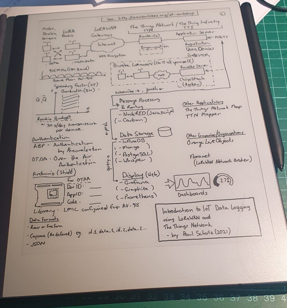
As a birthday present for myself earlier in the year I purchased a “reMarkable 2” e-ink tablet and it’s been awesome. More details about the device below (for those that are interested) but I recently had the chance to use it in a 1-1 meeting covering the PAE IoT Workshop and it worked really well as a paper notebook substitute. Afterwards I was able to go over the details, tidy them up, and rearrange them into a more sensible layout (rather than the original messy stream of consciousness).

Drawing on the reMarkable2

The tablet allows hand written text and drawings to be systematically edited, rearranged and replaced. There is the option on having layers (which I didn”t really use) and showing an underlying templete (lots to choose from) which is a useful guide for keeping everything nicely lined up, and which can be removed afterwards (replaced with the blank one).

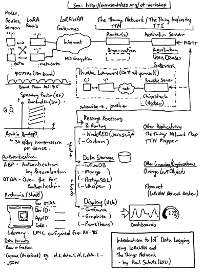
The final result can emailed as PDF, PNG, or SVG formatted files, and the result is below.

About IoT Data Logging using LoRaWAN

The following is an example of the path which might be taken by a packet of date, created on a LoRaWAN IoT device, as it makes it’s way from the sensor to be displayed on a web-based dashboard on the Internet.

About the reMarkable2

There is quite a lot to talk about with the reMarkable2 but where is a vary brief summary – it’s a Linux based ARM system, which has Wifi access and drives a e-Ink display with stylus for drawing and input. The display and pen software is closed source, but everything else appears to be Free and Open Source Software. It is possible to SSH into the device from both Wifi and USB-C, with a password that is displayed from the settings menu. If you wanted to you could use that the change any of the software on the device but beware – there be dragons.

reMarkable (the company) currently send out software updates regularly (almost monthly), as these also include new features and tweeks.

There are also third party projects (the reHackable project) which make the tablet even more useful, and support the use of the reMarkable in many more ways than the manufacturer may have intended, including replacing the entire operating system. I have not considered doing this just yet.