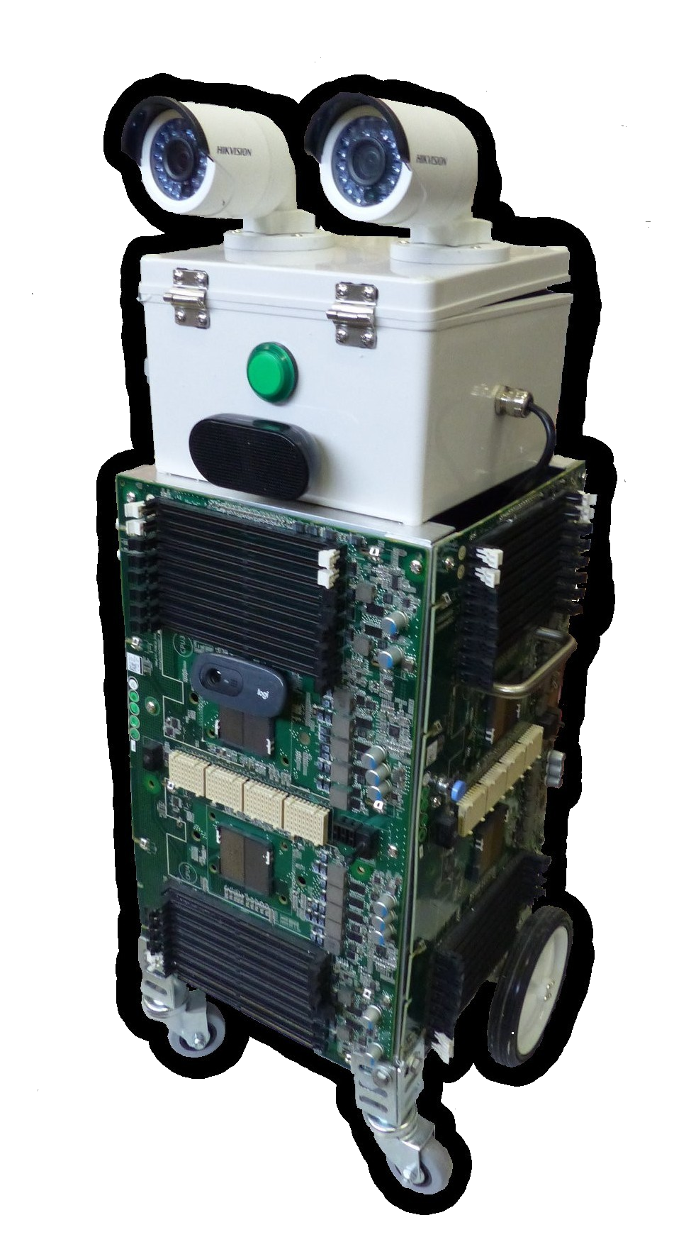
Another project for 2019! I am helping build robot rover with a “junk” theme (eg.make from e-waste) for use in school education program about recycling and reuse of electronic waste.
This is being done as part of my involvement as a volunteer with Port Adelaide Enfield Libraries and their STEM Program.
Robert has built the hardware which consists of a chassis made of old computer boards. The eyes are recycled IP security cameras which no longer work. The video is coming from a webcam, and the mouth is the usual set of stereo speakers sold for use with the Raspberry Pi computer. To control the motors and other moving parts, the Junkbot uses a small Raspberry Pi computer and a 16 Channel PWM PiHat from Core Electronics.
All of this work has been done with the aim of releasing everything under Free and Open licenses (both hardware designs and software). It would be great if the project reached a point where we not only made something useful for the STEM program but that others could use as a base for their own projects. (If any of this is useful to you, please let me know.)
All of the code from this project is available at Github.
The robot is running ‘Raspbian’ on the Raspberry Pi with the Python Libraries from Core Electronics to enable the wheel motors ans servos to be crontrolled via Pulse Width Modulation (PWM) and the attached PWM board.
For better or worse it was decided to create a keyboard control interface to drive the robot. The desktop screen of the Raspberry Pi is exported over Wifi and the internet via VNC, which can be accessed via VNCviewer. Using keyboard controls we can drive the robot motors, which also allowed us to then tune it’s operation.
As an initial observation, smooth driving operation of the robot might sound like a good idea but it appears as though with remote camera access, control is better if the robot makes small moves, allowing the video display to catch up.
Tuning, modifications and upgrades continue.
More about the construction
From Robert Hart on the electronics…

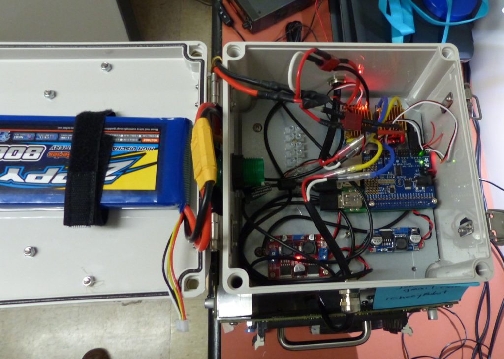
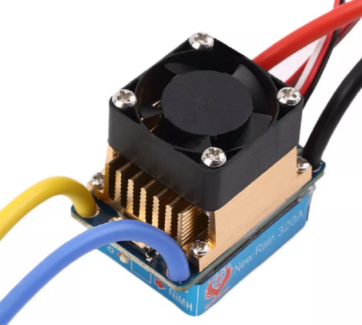
The robot will run on a S3 Lipo (on the left in the picture above). Its nominal voltage of 11.1V (3.70V*3 cells) and a fully charged 3S pack is 12.60V and a fully discharged 3S pack is 9.00V. I have incorporated two 5V buck (voltage) convertors: 5A for the Raspberry Pi and 3A for the Servo Hat. The two motors are driven using two Electronic Speed Controllers (ESC)

The ESCs have had the fans are removed and the on/off switchs have been removed and shorted. The servo lead has also had its postive wire open circuited so not to feed its 5V rail back into the Servo hat.
The Rasperry Pi and Servo Hat can be seen to the right of the box. The ESC’s are above that, with the two voltage converters at the bottom.
